Rust on STM32: Blinking an LED
DEPRECATED: I have created a more up-to-date version of this article. You can find it here !
GOAL: Blink the onboard LED on a BluePill board using Rust on a Linux Mint (Ubuntu based) machine.
Update/Information: The rustc version I used is rustc 1.31.1 (stable) and you need to install the ARM target with rustup target add thumbv7m-none-eabi beforehand.
I also put the code on Gitlab.
Preface
I have mainly used Atmel microcontrollers so far, but they are rather expensive, slow and have a totally confusing pinout. (And I think, they have no real future). So I wanted to use a better controller and setup the flow to program it on my Linux Mint machine (should work on Ubuntu as well). I assume, that the reader already has at least a little knowledge in Rust, Linux, and Microcontrollers
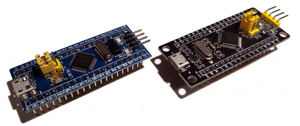
One of the possibly cheapest and general purpose boards is the STM32F103 board aka “BluePill”. These sell for less than 2€ on AliExpress, but I’d recommend you the more up-to-date version, the “BlackPill” (AliExpress), because the BluePill usually has a wrong resistor which causes trouble when using the USB port. Besides a slightly different pinout and the BlackPill being one row larger than the BluePill, they are basically the same.
Setting up the Cargo Project
First, we initialize a new Cargo project
> cargo init stm32_blink
> cd stm32_blink
We modify our Cargo.toml file as follows to include the required libraries:
[package]
name = "stm32_blink"
version = "0.1.0"
edition = "2018"

[profile.release]
# optimize for size ('z' would optimize even more)
opt-level = 's'
# link with link time optimization (lto).
lto = true
# enable debugging in release mode.
debug = true

[dependencies]
# Gives us access to the STM32F1 registers
stm32f1 = {version = "0.6.0", features = ["stm32f103", "rt"]}
# provides startup code for the ARM CPU
cortex-m-rt = "0.6.7"
# provides access to low level ARM CPU registers (used for delay)
cortex-m = "0.5.8"
# provies a panic-handler (halting cpu)
# (required when not using stdlib)
panic-halt = "0.2.0"
I the cortex-m-rt crate also requires a memory.x file, which specifies the memory layout of the board (See the documentation).
The documentation already provides the file for the BluePill as an example, so we only have to create the file memory.x with the following content:
/* Linker script for the STM32F103C8T6 */
MEMORY
{
  FLASH : ORIGIN = 0x08000000, LENGTH = 64K
  RAM : ORIGIN = 0x20000000, LENGTH = 20K
}
We can now compile the program using cargo rustc --target thumbv7m-none-eabi -- -C link-arg=-Tlink.x, but that would be a bit inconvenient.
Therefore, we create the file .cargo/config (and the folder .cargo) with the following content (based on this file):
[build]
# Instruction set of Cortex-M3 (used in BluePill)
target = "thumbv7m-none-eabi"

rustflags = [
  # use the Tlink.x scrip from the cortex-m-rt crate
  "-C", "link-arg=-Tlink.x",
]
Hoooray, now we can compile Rust code into an ARM elf file! (However, the code we have does not compile yet)
> cargo build --release
> file target/thumbv7m-none-eabi/release/stm32_blink
target/thumbv7m-none-eabi/release/stm32_blink:
ELF 32-bit LSB executable, ARM, EABI5 version 1 (SYSV),
statically linked, with debug_info, not stripped
The Blink Program
This is the content of the src/main.rs file:
// std and main are not available for bare metal software
#![no_std]
#![no_main]

extern crate stm32f1;
extern crate panic_halt;
extern crate cortex_m_rt;

use cortex_m_rt::entry;
use stm32f1::stm32f103;

// use `main` as the entry point of this application
#[entry]
fn main() -> ! {
    // get handles to the hardware
    let peripherals = stm32f103::Peripherals::take().unwrap();
    let gpioc = &peripherals.GPIOC;
    let rcc = &peripherals.RCC;

    // enable the GPIO clock for IO port C
    rcc.apb2enr.write(|w| w.iopcen().set_bit());
    gpioc.crh.write(|w| unsafe{
        w.mode13().bits(0b11);
        w.cnf13().bits(0b00)
    });

    loop{
        gpioc.bsrr.write(|w| w.bs13().set_bit());
        cortex_m::asm::delay(2000000);
        gpioc.brr.write(|w| w.br13().set_bit());
        cortex_m::asm::delay(2000000);
    }
}
Explanation:
#![no_std] is required, because we build a bare-metal application but the standard library requires an operating system.
#![no_main] tells the compiler that we don’t use the default main function with the argument vector and return type.
This wouldn’t make sense, since we don’t have an OS or other kind of runtime which would call the function and handle the return value.
Instead, the cortex_m_rt crate contains a minimal runtime and the #[entry] macro, which specifies our custom entry function (fn main () -> ! {}), which we call main as well (don’t be confused).
More information about bare metal software in Rust can be found for example in the “Writing an OS in Rust” Blog.
Inside the main function we create a handle to the peripheral object, which “owns” all the peripherals and registers with stm32f103::Peripherals::take().
rcc and gpioc are handles to the “reset and clock control” and GPIO register bank C (the onboard LED on my BluePill is connected to pin C13 but this might differ).
To use a pin as output we have to enable the clock for that specific GPIO pin bank by setting the IOPCEN bit in the APB2EN register.
Writing a byte in a peripheral register using the stm32f1 crate is done by calling the write function on that register struct (rcc.apb2enr.write()).
This function takes a FnOnce function as an argument.
The parameter which is passed to this function is in the first case of type gpioc::crh::W which implements functions to access the single bit fields in that very register (here: w.iopcen()).
This in turn has a function set_bit, which is used to set the bit in that hardware register and thus enabling the clock for the GPIO C bank.
The same applies for the CRH register, which is used to configure the pin as an output pin at highest speed (MODE=0b11 and CNF=00).
The bits function of the mode13 and cnf13 bit field is unsafe, but I can’t tell you why.
Therefore, we have to mark the functions inside the closure as unsafe as well.
Hint:
To get a documentation of the stm32f1 crate, generate it yourself with cargo doc --open
In the infinite loop, we write to the Port bit set/reset register (BSRR) and the Port bit reset register (BRR) to set pin C13 to high respectively low.
The delay function busy waits for at least the given number of cycles. The number here was just randomly taken and represents around 250ms.
The better approach would be to utilize the onboard timers, but for this simple example, delay is sufficient.
Creating the Binary
For the next steps, we need an ARM toolchain installed on our system. On Linux Mint (Ubuntu), this can be done with:
> sudo apt install binutils-arm-none-eabi
Update: I use the toolchain from the Ubuntu package manager. The toolchain which is installed with the thumbv7m target can also be invoked using Cargo (I’ll try this next time).
Optional: Disassembly
We can now view the disassembly of the elf file:
> arm-none-eabi-objdump --disassemble \
  target/thumbv7m-none-eabi/release/stm32_blink | less
So far, we only operated with the elf file. This format does not only contain the binary code but also some headers and stuff (see Wikipedia). This is useful, when another software like an operating system or bootloader launches the file. However, to run the program bare-metal we don’t need an elf file, but rather a bin file. This is an image of the software which can be written byte-by-byte into the memory of the microcontroller.
An elf file can be converted into a bin file with objcopy.
> arm-none-eabi-objcopy -O binary \
  target/thumbv7m-none-eabi/release/stm32_blink stm32_blink.bin
The stm32_blink.bin is now ready to flash.
Flashing the Binary
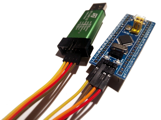
There are multiple ways to program the board, for example using the UART, using a USB bootloader (like the Arduino has), or using a programmer like an ST-Link. I’m using a ST-Link-V2 clone, which are almost as cheap as the Pill itself (AliExpress). You can even flash one yourself out of a BluePill/BlackPill.
Connect the 4 pins SWDIO, GND, SWCLK, and 3.3V on the programmer with the corresponding pins on the BluePill and plug it into your PC. Important: Disconnect any other power supply from the board, otherwise you can damage the board or in the worst case your PC.
There are other ways to program the board with the ST-Link, such as openocd, but I will use the open-source stlink tools. Unfortunately, this software is not available via the apt package manager, therefore we have to compile it from source.
# in a directory of your choice:
> sudo apt install libusb-1.0 libusb-1.0-0-dev
> git clone https://github.com/texane/stlink
> cd stlink
> make all
This creates the executables st-flash and st-info, which reside now in build/Release/.
There are different approaches to “install” these executables.
I will now copy them into a system folder.
However, it may be desirable to only copy them into a folder in your home directory which is added to $PATH or simply prefix all commands with the full path to the executable instead.
> sudo cp build/Release/st-{flash,info} \
  build/Release/src/gdbserver/st-util /usr/local/bin
> which st-info
/usr/local/bin/st-info
Optional: Udev Rules
To access the ST-Link without root permissions, copy the udev rules from the source code to /etc/udev/rules.d/
> sudo cp etc/udev/rules.d/*.rules /etc/udev/rules.d
> sudo udevadm control --reload-rules && udevadm trigger
We can verify the connection:
> st-info --descr
F1 Medium-density device
Optional: Erase existing software/bootloaders:
I had a stm32duino bootloader running on my BluePill, which lead to errors like WARN common.c: unknown chip id! 0x5fa0004 upon flashing.
To fix that, I had to erase the chip. This is done by executing the following command right after pressing the reset button on the board:
> st-flash erase
To flash the bin file, we execute:
> st-flash write stm32_blink.bin 0x8000000
st-flash 1.5.1-12-g30de1b3
2019-02-07T00:23:15 INFO common.c: Loading device parameters....
#[...]
2019-02-07T00:23:15 INFO common.c: Flash written and verified!
  jolly good!
Success!
Summary of Commands to Build and Flash the Software:
> cargo build --release
> arm-none-eabi-objcopy -O binary \
  target/thumbv7m-none-eabi/release/stm32_blink stm32_blink.bin
> st-flash write stm32_blink.bin 0x8000000
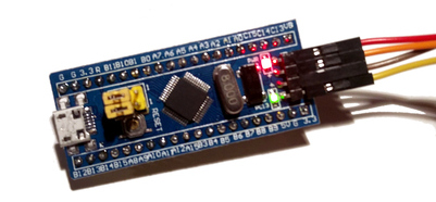
That’s it! Now the LED on the board is blinking!


